FastSHAPES <Modules
FastSHAPES® is the generic name for a suite of geometric Development Modules suitable for both sheetmetal and plate I.E. thin and thick materials. SHAPE programs are most suitable for heavier fabrication where the main jointing technology is welding.
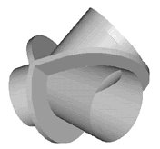
The BIFURCATE provides patterns for the developed plates used in smaller scale bifurcations where typically plate thickness does not vary throughout the structure, but are still significant. Plate development needs to consider the various welding details and edge preparations required for economical plate cutting and fabrication. The structure is set out using the method of common central spheres. Development uses the radial line method. Weld preparations may be specified at all joints, and patterns provide for marking intersection lines at weld prep. depth, inside surface intersections, and outside surface intersections. The purpose of such marking is to facilitate preparation for welding, frequently undertaken as a secondary operation. Each of the three branches exist as a simple cone, and may be developed in up to 4 segments. Green may be added to any or all edges of each individual segment. Patterns may be arranged to defer cutting until after rolling when the development involves significant variation in plate width for rolling. Patterns include marking of rolling guides (generators) and constant curvature lines. Match marks for inside and outside of bend, and top & bottom dead centre. Note: Larger, heavier and more generally setout bifurcates are handled by BifurcatePlus.
|
|

 DATA REQUIREMENTS
 Branch Diameters, Angles, Lengths.